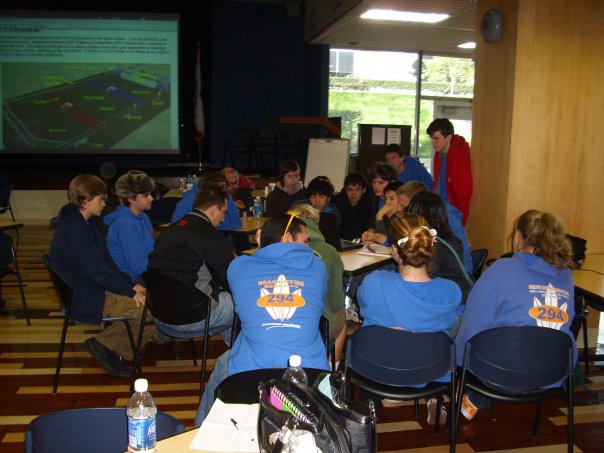
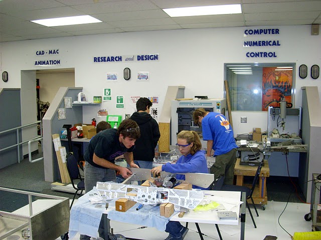
After the kickoff video broadcast, the students and mentors study the rules.
FRC robots must be designed to play a new and different game every year, unveiled at the annual kickoff,generally held on the first Saturday in January. After the unveiling of the game, student teams havesix weeks to design, fabricate, assemble, program, and test their robots. The robots must be lockedin their shipping containers and delivered by the deadline, or the team does not compete. This year,over 2,000 FRC teams from around the world met that deadline. The flags of 31 nations were flyingin the Georgia Dome at this year's Championship.
Robots this year can be no more than 36 inches long 28, inches wide, and 60 inches high, in theirstarting configuration. They can expand out of this envelope during the "finale" portion of thegame (last 20 seconds) or some other conditions. Robots must have bumpers on all four sides about10 inches off the floor so they don't interfere with the regulation soccer balls that are a littleover nine inches in diameter. Robots can weigh no more than about 150 pounds including battery andbumpers.
This year's 294 build season is documented here,and links to this year's competitions are here.
Students are active in recruiting team members from the schools' student bodies by participatingin club day and other high school events on campus. Our students are trained in our workshops inpublic speaking by a professional trainer who volunteers her time so our students can give effectivepresentations and are well spoken when talking with news media people.
Our award-winning FLL team brings students into the FIRST culture at a younger age and gives thempractical training in robot development and programming that will serve them well when they graduateto the high school FRC team.
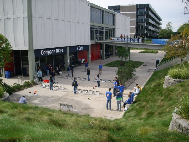
On the day of the kickoff, we simulated the gameusing students acting as robots on a field contrived from the outdoor furniture available at thekickoff venue. Each student robot was assigned one or two capabilities (grab, kick, move the ball)and virtual (as in a chess game) time was used. On each beat of the clock, a student would performa featured action. This allowed us to get a sense of what was important in winning a game.
From our analysis of the game we concluded that the game would be decided on the midfield, where allscored balls are returned by the ball return mechanisms. A good midfielder robot would be able to getto a ball quickly, grab it easily, and kick it into the near scoring zone, preferably directly into agoal. We also wanted enough flexibility to be able to score in the near zone, and to start in anyof the three zones with an effective autonomous mode. Our preferred starting position was in thefar zone, where we would autonomously kick three balls into the near zone goal, and then climbover the bump into the midfield, ready to grab the returned balls.
In deciding the robot design we had to do some down selection. First after studying thegame using the simulations, etc., we had to decide on what type of robot we wanted to build. This led us to a decision to evaluate three distinctly different robots. Essentially the studentssaw that there were different roles that a robot could fulfill. We could have built a striker (nearzone scoring robot), a midfielder, or a purely defensive bot. The students listed the featuresthat would be needed to build a successful robot for each role. For each role the students listedthe features that were needed for that robot. For example the defensive robot needed a large kick,it needed to be able to go over the bump, and it needed lots of traction. The stiker needed only asmall kick, it needed to be fast, and it needed good ball control.
The students then needed to decide what role we wanted to play. Based upon the simulations thestudents figured the smartest strategy was to design a midfielder robot. While providing versatilityto play both offense and defense, it also had the most features of the three roles. From there wewrote down to the feature list that we thought would make a perfect robot to fulfill the role.This included good ball control, multi-zone traversal, hanging, dual zone ball kicking, good mobilityand good wheel torque (for pushing other robots and resisting being pushed). Due to manpowerconstraints and design limits, the students voted that the lift would be removed from the midfielder. We felt that with the amount of students we had we could meet the other requirements that we had written.Thus was born the midfielder design we wanted to achieve.
We made a conscious decision not to include a hanging mechanism because we knew we would have a massproblem, and the added complexity would tax our design, fabrication, and assembly resources. We alsofelt that in the last 20 seconds of a game, while other robots were hanging, we could probablyscore one or two balls.
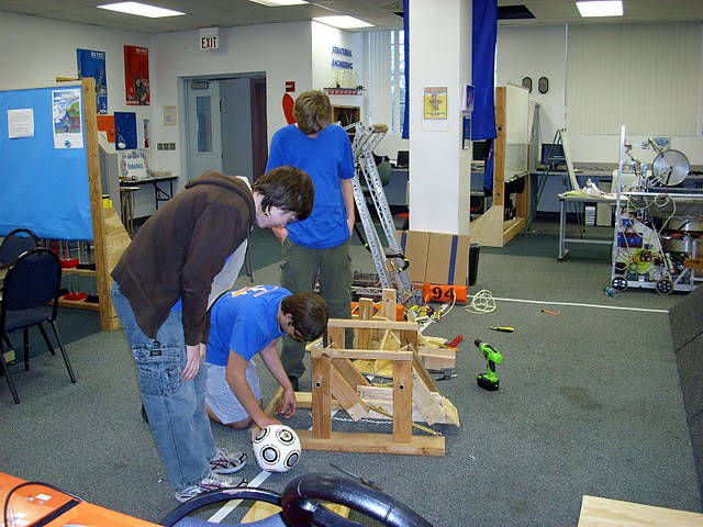
We created a schedule for the six week build period. We wanted to have initial robot designsdone in the first two weeks to start fabrication of some critical parts, to have all design doneby four weeks, and to have assembly completed by five weeks so we could turn the robot over to theprogrammers for software testing. We generally met those goals.
We built two copies of the robot so that after we shipped the competition robot, the drive teamcould practice, the programming team could experiment with software, and we could prototypeimproved mechanisms. We were allowed to withhold 65 pounds of mechanism from the robot shipping crate.
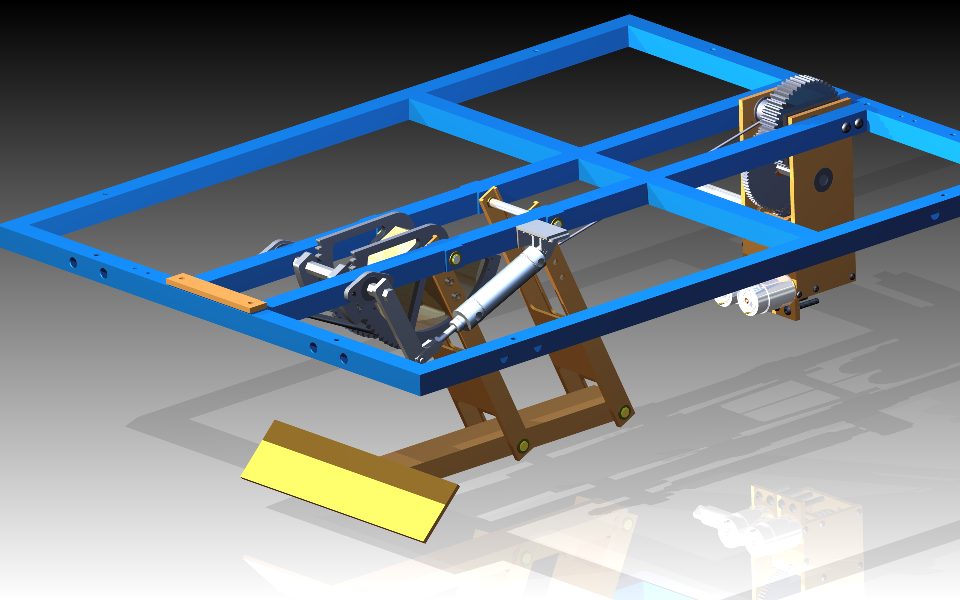
The entire robot was designed in Autodesk Inventor, a 3D solid modeling comuter aided design (CAD)program. Due to our summer workshops and fall training programs, we have at least six studentsproficient in CAD, and every part was designed and a part drawing was produced before fabrication.We have access to four computers that are CAD capable, two destop computers and two laptops. Wehave a file server for coordinating the design on the several machines. The drive base design wascompleted first, with envelopes and interfaces for kicker and grabber mechanisms. This allowedus to begin drive base fabrication before kicker and grabber detailed designs were complete.
We finally settled on a four bar linkage,which had the most consistent results because the angle of attack on the ball is held constant.
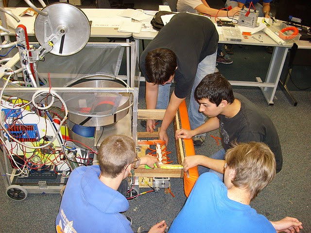
We prototyped a vacuum system that would be able to suck the ball into the correct spot. Due totesting limitations we were unable to get a fully functional ‘sucker’. We also tried rollers. Thekey experimentation with the roller was the grip, the torque, and location the roller was in.We built a prototype that allowed the different variables to be tuned. Material was varied usingdifferent rollers. The power was adjusted in a cordless drill to modify the speed/torque. Finally,the height was adjusted to simulate contact at different ball heights. From the testing wediscovered one of the most important things that carried through even to the pincher design.This was the nee for a backstop to prevent the ball from being sucked in too far into the robot.The backstop provided a means to never violate the three inch rule (that limits ball penetrationinto the frame perimeter). The prototype testing also let us determine the gear ratio that weused in the robot's roller gearbox. This was done by looking at the gearing and rough free speedof the drill. We then matched gearing to properly accommodate a CIM motor.
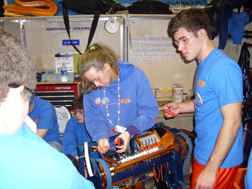
The new grabber used a small diameter friction roller driven with a friction clutch so that themotor would continue turning, but the roller would stop and hold the ball statically. When thathappened, motor current would increase, causing the computer to send a signal to the driver's stationto give the LED indication. We won the Innovation in Control Award at the LA Regional for our grabbersystem.
The kicker was pulled toward the front of the robot by elastic material with about 80 pounds ofpeak force. To energize the kicker, it was pulled back by a cable and winch driven by two electricmotors through a reduction gearbox. Two motors were used to increase the speed of energizing betweenkicks. The kicker would be held in the energized position by a ratchet and pawl controlled by apneumatic cylinder. To release the kicker, the pawl would be pneumatically disengaged after thewinch was reversed to give slack. It was a fairly complex method, but computer control allowedthe co-driver to operate it with a fairly simple interface, made possible by the feedback sensorson the kicker. We used two limit switches and an encoder. The limit switch on the front woulddenote a zero location to return the kicker to the same time. This was only used in debug/postmatch. The back limit switch prevented the kicker in over ‘arming’ and breaking itself. The encoderon the kicker gearbox would then be used to define the exact location in the ratchet to which the kickerwas being armed.
We used black surgical tubing as the energy storage medium for the kicker initially, but, afterthe San Diego Regional, we changed it to a set of flat rubber sheets to get more energy (higherenergy density) for a more powerful kick.
Before the FRC Championship in Atlanta, we improved our kicker by strengthening the ball interfacebeam, and reducing the kick angle from 45 degrees to 20 degrees for a flatter kick to make iteasier to hit the goal at close range. Hitting the goal at a low height was important because thechains hung across the goal would reject balls hitting the goal opening higher up.
During robot development, we had some trouble getting the kicker to work at all. The ratchet and pawlwas not the first design, which was to utilize a dog gear/clutch to allow the kicker gear box tobecome decoupled with the kicker mechanism. The problem was that we were afraid that the hightorque loads on the dog clutch would prevent the pneumatic piston from pulling the clutch out.To mitigate this we moved the clutch further into the gear box, which was a fatal flaw because oncethe dog was released all the stored energy was then transmitted into the rotation of all the gearsin the gearbox, making the kick very weak. The ratchet and pawl were then designed as fix to allowkick variability even if it locked into a single kick strength once armed. The ratchetsystem worked beautifully.
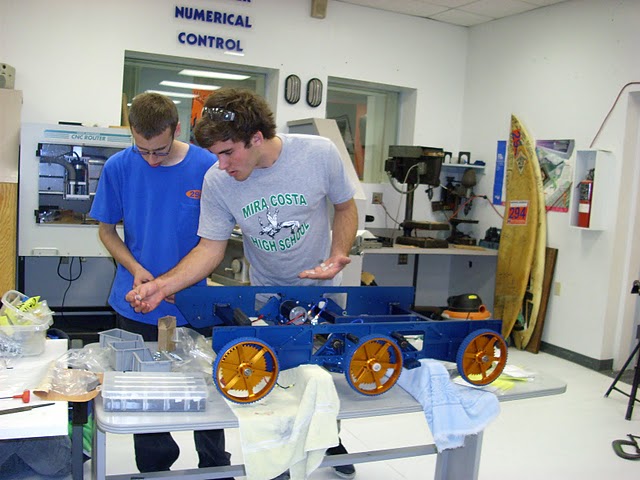
The next design to be completed was for the drive train side plates.Each robot had four identical plates. We used forward-aft symmetry to minimize NC machine setup time.The 1/4 inch thick plates were pocketed for lightening with a sixteenth inch web.
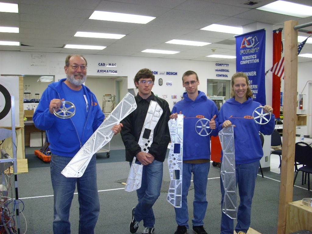
Two side plates were used to hold the three wheels and chain on each side. The two sides were held together with transverse memberswelded by a volunteer at Northrop Grumman (Mike Utley). We had two partially assembled drive basesin week five. We had a fully assembled and running drive basein week six. The drive base has a two speed transmission, shifted pneumatically, under computer control.Our student team captain, Ryan Sharp, arranged for a sponsor to donate annodizing, so the aluminum parts were anodized blue and orange,the team colors.
For the twelfth consecutive year, Beach Cities Robotics designed, built, and shipped a competitive robotin six weeks!
The co-driver had 3 buttons for selecting different kicker strengths. One of these buttons wasfortunately also the zero position. The co-driver also had buttons to arm the kicker (engaged the
ratchet and unwind the winch to the fully unwound position) and fire it. Software interlocks
prevented firing before the cable was fully unwound (this was the cause of several cable breaks
in our first practices). The codriver also had buttons for adjusting the kicker strength by a
single ratchet tooth up/down and a manual override which allowed driving of the winch directly
(overriding the PID control) using the vertical axis on the joystick. The rezeroing limit switch feature
was used only during manual drive of the winch.
Ball detection in our intake was determined via internal current sensing on the Jaguar, read via CANbus. Due to the clutch, the current was significantly higher (30A) with a ball than without (4A). The currentdraw ended up being a significant drain on our batteries, so we added a timeout that would reduce motorpower on the intake when stopped or driving forward after the ball had been detected for 1 second. The motor power was just sufficient to turn the CIM (instead of stalling it) and resulted in a currentof around 20A in the low-power mode.
We were top seeded in the Newton Division at the Championship competition. It was extremely importantthat we pick good alliance partners. If a team declines to accept an invitation to join an alliance,it may not accept another invitation. This applies to alliance captain teams, which lose theircaptain status if they accept an invitation from a higher seeded team. Therefore, before choosingteam 67 (The HOT Team, Michigan, seeded second) as our first pick, we needed to approach them to assesstheir intentions before taking the field for alliance partner choosing. The order of choosing is"serpentine," that is, the order for alliance selection is 1, 2, 3, 4, 5, 6, 7, 8, 8, 7, 6, 5, 4, 3, 2, 1to try to balance alliances. In other words, the top seeded team gets the last second pick. That meansthat we needed a very good understanding of the strengths and weaknesses of the available teams (86teams total in the Newton Division). The only way to get that information was for our scouting subteamto observe the robots on the field during the qualifying matches.
We had six students on the scouting team with two relief students, advised by the scouting mentor, theauthor of this article. The scouting team captain was Matt Steiger, a student at Mira Costa High School.The six students used laptop computers to record data about robot performance (balls scored, etc.),one for each of the six robots on the field at a time, recording data for all the qualification matcheson Thursday and Friday. We held a meeting Friday night to compile the data and discuss it with therest of the team, and make our recommendations in the form of two lists of midfielder and "striker"(near zone scoring) robots.
We decided that the winning alliance would have two midfielder robots (like ours) and a thirdmidfielder or striker (assuming that most good midfielders were also good strikers). As it worked out,team 67 accepted our invitation to join our alliance, and team 177 (Bobcat Robotics, Connecticut)turned out to also be a good pick.
Beach Cities Robotics continues to work to achieve the goals of FIRST in changing our culture tocelebrate achievement in science and technology, and to inspire youth to pursue careers and educationin math and engineering. This is demonstrated by the fact that in the last eight years, 100% of ourgraduates have gone on to pursue college education.
Rick Wagner, April, 2010, Redondo Beach, California, USA.
Copyright 2010-2021 by Dr. Rick Wagner and Beach Cities Robotics. All rights reserved.
Scouting, Strategy, and Competition
The fact that the game is played by alliances (red and blue) gives added dimensions to strategy,including a political one. A competition consists of a series of qualification matches in whichthe alliances are more or less randomly assigned (certain constraints in the assignment algorithmpreclude teams from playing matches too close together in time, for instance). Each team carriesforward the points (a summation) that the alliance achieves. At the end of the qualification matches(each team plays seven to ten, depending on the competition), the eight top seeded teams are allowedto choose their two alliance partner teams. This is where the politics comes in. A team may choosea team it feels it can work with better, rather than considering only the strength of the robot anddrive team. Also, teams may choose alliance partners that complement their playing strengths andweaknesses.Conclusion
We first won the FRC Championship in 2001. After nine years, we have won it again. But it's not justabout the robots. It's about teamwork, and about learning skills such as computer aided design (CAD),engineering calculations, fabrication, assembly, algorithms and programming, management, fundraising,community outreach, and all those things it takes to compete and win with gracious professionalism.Acknowledgements
I wish to thank UC Berkeley Professor Ken Goldberg for suggesting the writing of this article.
Andrea Wagner (team coordinator) proof read the article and provided valuable comments. Naturally,
it goes without saying that this article wouldn't be possible without the awesome team 294 itself,
with all the hard work in designing and building the robot, with all the long hours by our students,
mentors, and sponsors. In particular, students Ryan Sharp, Anton Schuetze-Coburn, and mentors Andrew
Keisic (lead technical mentor), Peter Johnson, and Ken Sterk, were instrumental in producing the
Championship winning robot. Ken and Peter also contributed to the text of this article.
WinningChamps.html, this hand-crafted HTML file was created April 12, 2010.
Last updated August 10, 2021, by Dr. Rick Wagner.